
Invention of the Yagi-Uda antenna
Prof Dr Dieter Brückmann / Communications Engineering
Photo: UniService Third Mission
Transducer between the waves
Communications engineer Dieter Brückmann on the invention of the Yagi-Uda antenna
In 1926, the first reports appeared in a Japanese magazine about the Yagi-Uda antenna, which was developed at the Imperial University of Tohoku in Sendai. What was this device and who developed it?
Dieter Brückmann : To transmit electromagnetic waves via radio, you need an antenna both on the receiving end and on the transmitting end. Antennas are converters between a conducted wave and a free-space wave. Antennas therefore either emit electromagnetic waves generated by a transmitting device or receive electromagnetic waves and transmit them to a receiving device. The simplest form of antenna is a dipole. A dipole antenna typically consists of two conductive metal wires or rods. The drive current coming from the transmitter is applied between the two halves of the antenna. On the receiving side, the received signal is tapped at the antenna and forwarded to the receiver.
One possible disadvantage of a dipole antenna is that the energy of the electromagnetic wave is radiated equally in all directions around the antenna. In many cases, however, it would be more favourable to give the transmitting antenna a directional effect so that the energy is radiated in a bundled manner. The antenna arrangement can also generate focussing in the direction of reception, thereby amplifying the signal compared to a dipole antenna.
The Yagi-Uda antenna is an antenna system that generates such a focussing effect so that significantly greater radio transmission ranges are possible compared to dipole antennas. This type of antenna was developed from 1924 by the Japanese Hidetsugu Yagi and Shintaro Uda and the process was also described in Japanese technical journals. However, these reports initially attracted little attention outside Japan. In 1928, Yagi therefore also published an article in English in the USA, which met with great interest among experts worldwide. This also explains why this type of antenna is usually referred to as a Yagi antenna in German-speaking countries. While the Japanese patent lists both inventors equally, only Yagi is named as the inventor in the basic patents for other countries.
In 1930, the antenna was shown for the first time in Europe at the World Exhibition in Belgium. What range did it have?
Dieter Brückmann: The system with the Yagi-Uda antenna that was shown at the 1930 World Exhibition operated with a wavelength of 45 cm. This corresponds to a frequency of 666.7 MHz. The system presented enabled radio transmission over a distance of up to 20 kilometres.
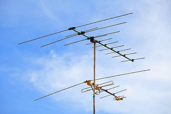
Roof-mounted aerial
Photo: Colourbox
How does an antenna actually work?
Dieter Brückmann: An antenna is used to transmit or receive electromagnetic waves and acts as the interface between the transmitter or receiver and free space, which serves as the transmission medium. Its basic structure consists of conductive elements, such as one or more metal rods, which are connected to the wired transmitting or receiving equipment via an antenna cable. The simplest form of an antenna is a dipole consisting of two wires. The dipole can also be regarded as an open oscillating circuit. Feeding the dipole with a varying electrical signal creates an electromagnetic field that is radiated into space. Similarly, on the receiving end, the received radio signal induces a current in the dipole. This utilises the principle of resonance.
To achieve efficient transmission, the length of the antenna is tuned to the wavelength of the signal. Variations in antenna design allow it to be adapted to different frequency ranges and applications. In particular, the parameters of size, shape and configuration are adjusted. For example, the antenna is made directional by means of one or more directors and, where appropriate, reflectors. This directivity is also associated with antenna gain, which corresponds to an amplification of the signal. This principle is utilised in the Yagi-Uda antenna.
The Yagi antenna was frequently used during the Second World War. For what purpose?
Dieter Brückmann: During the Second World War, the Yagi-Uda antenna was frequently used for radar applications. Radar was a revolutionary invention at that time and fundamentally changed the military strategy of all the warring parties during the Second World War. Radar uses radio waves to detect and locate aircraft, ships and other objects. This made it a very important tool for air defence, naval warfare and also for military operations on the ground. In addition to the classic Yagi-Uda antenna design, variants featuring parabolic reflectors were also used. Due to the directional nature of the Yagi-Uda antenna, the angle of rotation can be used to determine the direction in which the detected object is located.
In the 1950s, the benefits of the Yagi antenna were also recognised for television, weren’t they?
Dieter Brückmann: After the Yagi antenna had been used during the Second World War, particularly in the military sector, it spread very quickly in North America and Europe, including within the amateur radio community. The main reasons for this were its simple design, which is also suitable for DIY construction, and its high antenna gain. Furthermore, from the 1950s onwards, this type of antenna was also used increasingly frequently in commercial applications such as television. Particularly on the fringes of television broadcasters’ coverage areas, the Yagi antenna was frequently used due to the antenna gain resulting from its directivity. By using a Yagi antenna, many television viewers in East Germany were also able to receive West German television programmes if they aligned their Yagi antenna in the correct direction.
Yagi antennas come in various sizes. Why, for example, does a radio need a longer antenna than a Wi-Fi device?
Dieter Brückmann: The basic element of a Yagi antenna is a dipole, which, for optimum performance, should be just under half a wavelength of the radio wave to be received. The other elements of the antenna – the directors – should be slightly shorter, and the reflectors slightly longer than the dipole. The directivity and antenna gain are determined by the total length of the antenna. A three-element Yagi-Uda antenna with a total length of 0.3λ can achieve an antenna gain of approximately 15 dBi, with a beamwidth of less than40 °. Even more powerful Yagi antennas have up to 10 rod elements.
Typical FM radio waves lie in the frequency range of 87–105 MHz. This results in a wavelength of approximately three metres. The corresponding antenna should therefore be at least one metre long. Wi-Fi devices, on the other hand, operate in significantly higher frequency bands in the range of 2.4 GHz or even 5 GHz. This results in significantly shorter wavelengths of 6 to 12 centimetres. The optimal antenna lengths for this application are therefore in the range of just a few centimetres.
Is it actually true that you can easily build a Yagi antenna using materials from a DIY store?
Dieter Brückmann: One particular advantage of the Yagi antenna lies in its simple construction and robustness. It has long been known amongst DIY enthusiasts that a robust Yagi antenna can be built using simple metal rods and a few connecting materials, all of which are available at a DIY store.
Whilst building a Yagi antenna for TV reception or amateur radio applications requires a fair bit of technical skill, specialist magazines and the internet now even feature DIY guides for polystyrene Yagi antennas for Wi-Fi systems. These can reportedly be put together in just half an hour using leftover packaging and electronic scrap.
With the trend towards wireless transmission, more antennas are being sold again these days. Where are they mainly used nowadays?
Dieter Brückmann: The number of applications in which radio transmission systems are used has increased significantly in recent years, and will continue to grow in the coming years. Each of these wireless systems is equipped with an antenna. As the requirements and applications can vary considerably, a wide variety of antenna systems are needed to meet these diverse needs, meaning there is now a wide range of basic types and variants available.
In the case of Wi-Fi systems, for example, the requirements for very high data rates have risen sharply in recent years. These high data rates can be achieved in particular through multi-antenna systems and MIMO technology. MIMO stands for Multiple Input / Multiple Output. With this technology, multiple antennas are used on both the transmitter and receiver sides, between which parallel data streams are transmitted. In this way, the maximum data rate can be multiplied. Sophisticated digital signal processing on the receiving end compensates for the mutual interference between the parallel data streams.
Furthermore, the importance of electronically steerable directional antennas is growing steadily. These consist of a number of dipoles whose fields overlap, thereby creating directionality. Furthermore, the phase shift between the antenna signals can be varied electronically, allowing the radiation pattern of the antenna array to be precisely adjusted. Antenna arrays comprising over 1,000 dipoles are now in use, enabling the radiation pattern to be varied in as many as three dimensions. Applications include systems based on current and future mobile communications standards from 4G to 6G. This enables the subscriber density and the maximum data rate of these systems to be further increased.
Uwe Blass
Prof. Dr.-Ing Dieter Brückmann headed the Department of Communications Engineering, Components and Circuit Technology in the Faculty of Electrical Engineering, Media Technology and Information Technology at the University of Wuppertal until 2023.